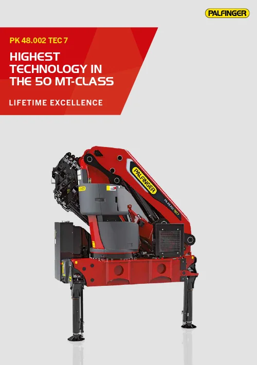
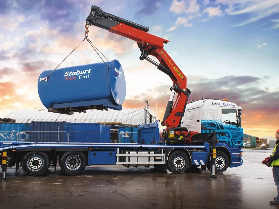
PK 48002 TEC7
- Very stiff and light boom system thanks to P-Profile
- More efficient and faster due to continuous slewing system
- High user friendliness due to in-house developed radio remote control PALcom P7
- More efficiency with fly-jib due to DPS-C
- Maximum utilisation of the working range thanks to extended HPSC
- More lifting power due to S-HPLS
- Practical and attractive due to Functional Design
P-Profile
The polygonal or drop-shaped P-Profile is especially rigid and simultaneously light weight design perfection. Thanks to self-lubricating materials, the extension boom system is low in maintenance.
High Power Lifting System
The PALFINGER High Power Lifting System (E-HPLS, A-HPLS or S-HPLS) increases the capacity of the crane by up to 15% while reducing working speed. E-HPLS can be activated manually for the occasional manipulation of very heavy loads. A-HPLS as well as S-HPLS are activated fully automatically. There is continuous activation depending on the power required.
Read MoreExperience The Product Features

HPSC
PRODUCT FEATURES
The High Performance Stability Control (HPSC) is a fully proportional system for monitoring the stability of the crane vehicle. Sensors for proportional path measurement in the stabilizer supports permit completely variable support positioning. Hence, the permissible, safe working range can be calculated for any support situation.
HOW IT WORKS
The HPSC system calculates the permissible working range for any slewing angle of the boom system and for any support situation. The position of the stabilizer support is detected by means of a cable extension transducer or magnetostrictive position sensor. Based on the intelligent calculation algorithm developed by PALFINGER, it works more efficiently than comparable systems that are available in the market.
AOS
PRODUCT FEATURES
The patented PALFINGER “AOS” oscillation suppression system cancels out vibrations and blows that occur during crane operation. Any “post-oscillation” is prevented through rapid braking or load changes. The result is a decisive increase to safety in crane operation for employees, the load and building.
HOW IT WORKS
The electronics receive signals from pressure sensors on both sides of the elevating cylinder and interpret them as arm vibrations. The signals for the counter-movement of the elevating cylinder are handled by the control valve. The incurred vibration can be cancelled through the exactly determined frequency and wavelength. The result is damping of the arm to just one or two short vibrations so that the arm comes to an immediate standstill.
* Optional feature/country-specific-equipment
DPS Plus
PRODUCT FEATURES
The Dual Power System (DPS Plus) makes it possible to use the full lifting power of the fly-jib through the use of two pressure ranges on the fly-jib. With it the full lifting power of the fly jib can be used also for crane-jib combinations with a very long outreach if the crane’s extension boom is not completely extended.
HOW IT WORKS
The fly-jib can also be operated with two pressure ranges through the use of a special electronic overload cut-off. If the last extension boom of the crane is extended (normal operation), then the lifting power is reduced to protect the crane against overloading. If the last extension boom of the crane is retracted (DPS Plus active), then the system switches automatically to the high pressure range thereby using the full lifting power of the fly-jib.
* Optional features/country-specific-equipment
SRC
The SRC system maintains a constant distance between the pulley head and the hook block during operation of the rope winch. Similarly to the RTC, the system automatically adjusts the rope length. The key advantage in practice is that loads can be traversed horizontally at a constant height without the operator having to adjust the rope winch. In addition, it is also possible to traverse the load at a constant angle on the rope winch. Work in buildings or tight spaces become child’s play, and difficult operations like overcoming building contours during roofing work are also made significantly easier. This advantage is particularly valuable in terms of ease of use for the operator, and it also noticeably improves the efficiency of any assignment. In addition, the risk of damage to the rope and load, but also collisions between the hook block and the pulley head will be avoided.
* Optional feature/country-specific-equipment
Technical Data
| Max. lifting moment | 45.7 mt |
| Max. lifting capacity | 16500 kg |
| Max. hydraulic outreach | 21.2 m |
| Max. manual outreach | 25.9 m |
| Max. outreach (with fly jib) | 33.9 m |
| Slewing angle | ∞ |
| Slewing torque with 1 gear | 4.0 mt |
| Slewing torque with 2 gears | 5.2 mt |
| Stabilizer spread (std) | 7.8 m |
| Width folded | 2.55 m |
| Fitting space required (std) | 1.43 m |
| Max. operating pressure | 385 bar |
| Pump capacity | 90-120 l/min |
| Dead weight (std) | 4300 kg |
Cranes shown in the leaflet are partially optional equipped and do not always correspond to the standard version.
Country-specific regulations must be observed. Dimensions may vary. Subject to technical changes, errors and translation mistakes.
(mt) | (m) | (°) | (mt) | (MPa) | (l/min) | (kg) | (mm) | (mm) | (mm) | |
| A | 42.7 | 7.9 | ∞ | 4 | 38.5 | 90-120 | 4300 | 2460 | 2550 | 1440 |
| B | 41.5 | 9.9 | ∞ | 4 | 38.5 | 90-120 | 4530 | 2460 | 2550 | 1440 |
| C | 40.8 | 12 | ∞ | 4 | 38.5 | 90-120 | 4780 | 2460 | 2550 | 1440 |
| D | 40 | 14.3 | ∞ | 5.2 | 38.5 | 90-120 | 5030 | 2460 | 2550 | 1440 |
| E | 39.4 | 16.6 | ∞ | 5.2 | 38.5 | 90-120 | 5240 | 2460 | 2550 | 1525 |
| F | 38.7 | 18.9 | ∞ | 5.2 | 38.5 | 90-120 | 5450 | 2460 | 2550 | 1525 |
| G | 38.3 | 21.2 | ∞ | 5.2 | 38.5 | 90-120 | 5580 | 2460 | 2550 | 1525 |
The outreaches stated are with a boom angle of 20° and are therefore not the maximum. When using mechanical boom extensions, the loads shown on the charts need to be reduced by the weight of these extensions.